Preventive Maintenance
Recapping the Ultimate 106
The Ultimate 106 PCB contains 43 electrolytic capacitors. Units are now 25 or more years old, and electrolytic capacitors have a finite service life — particularly in equipment that runs continuously or is subject to thermal stress. A full recap is a worthwhile preventive measure, and will address the ringing circuit fault described on the Fault & Fix page as part of the process.
View the Ultimate 106 Component Parts Database →
Capacitor Location Map
The photograph below shows all 43 electrolytic capacitors on the main PCB. Two label colours are used:
- Yellow labels — the PCB silkscreen reference (e.g. C22, C17) is visible on the board and can be read directly.
- Green labels — the silkscreen reference is printed underneath the component and cannot be read without desoldering it. These have been assigned temporary letter references (A, B, C…) which are cross-referenced in the parts database.
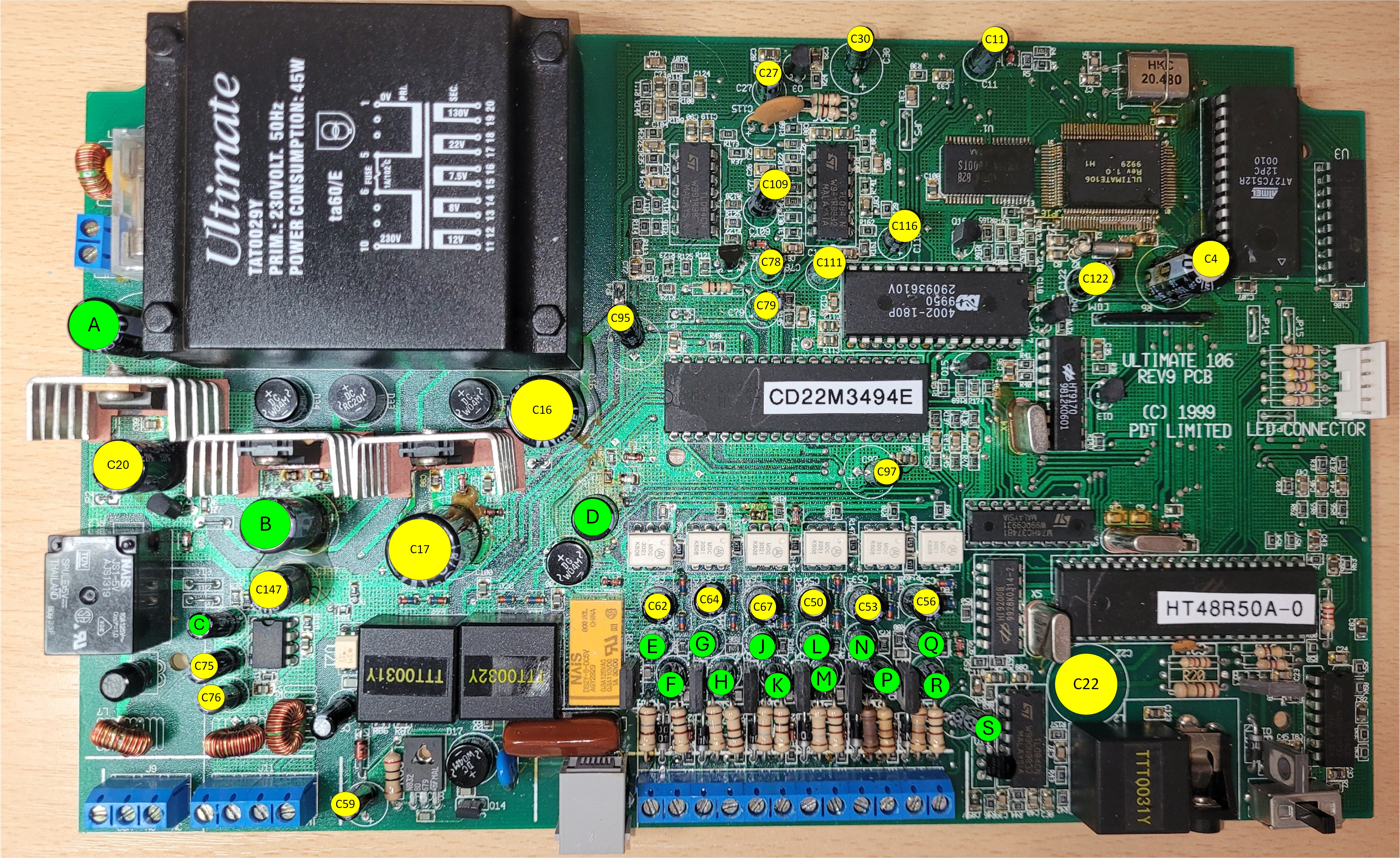
All 43 electrolytic capacitors annotated. Click the image to enlarge. Yellow = silkscreen reference visible; Green = reference hidden under component, temporary letter assigned.
Approach to Recapping
For anyone undertaking a full recap for the first time, a methodical one-at-a-time approach is recommended — replace each capacitor individually rather than removing them all first. This avoids the risk of losing track of orientation or position, and means the board remains testable at each stage.
General tips
- Work in a logical order across the board — for example, left to right, top to bottom. The annotated photograph above and the parts database together provide a complete map.
- Note polarity before desoldering each capacitor. Electrolytic capacitors are polarised — the negative lead is marked with a stripe on the body, and the positive lead hole on the PCB is typically marked with a + symbol or square pad. Photograph each one before removal if in doubt.
- Replace one at a time — desolder the old capacitor, clean the pads, fit and solder the replacement before moving to the next. This keeps the board organised and testable throughout.
- Use good quality replacements — brands such as Panasonic (FR/FC series), Nichicon (Fine Gold / PW series), or Rubycon are well regarded for longevity. Avoid no-name capacitors which may have similarly short service lives.
- Check lead pitch before ordering — as noted on the Fault & Fix page, modern capacitors at higher voltages (particularly 200V) are often manufactured with a 5mm lead pitch rather than the 7.5mm of the originals. Check the parts database for notes on individual components where this is known to be an issue.
- Pay particular attention to the high-voltage capacitors in the power supply and ringing generator areas. These operate under the greatest electrical stress and are the most likely to have degraded. C22 in the ringing generator is the most critical — see the Fault & Fix page for full details.
- Clean flux residue from the solder side of the board after completing the recap, using isopropyl alcohol (IPA) and a soft brush.